Week 7: Electronic Output Devices
Table of contents
This week I was humbled by simple electronics.
Since I already used the OLED in week 4, this week I decided to play around with microphones this week (although technically an input device, I got permission to use the microphone on output device week). This article will be a diary of how I was humbled by simple electronics…
Idea 1: Audio recording and playback
My first idea was to create a speech recorder that played back on a speaker using the parts we had in the lab. The first step is to get the microphone working.
Getting the microphone to work
SPW2430 MEMS Mic
We have three kinds of microphones in the lab, the first one I tried was the SPH2430 MEMS microphone. I connected the microphone to the ESP32, ran some tests to see if it would pick up a simple sine wave played from my iPhone. It did not… Thinking that I may just have a faulty unit, I tried again with another one and it also didn’t work.
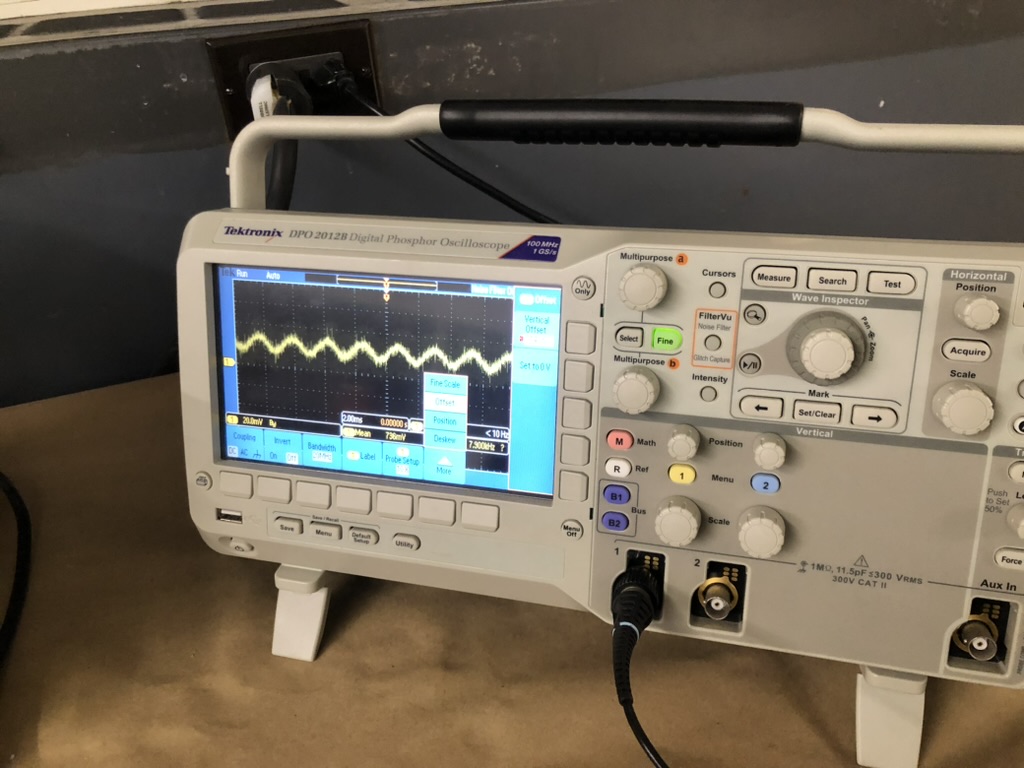
To figure out why it wasn’t working, I turned to the oscilloscope and read the technical specifications. The manual says that the microphone has a 0.67V bias and the absolute maximum peak-to-peak it can record is 1V. Hooking up the microphone to the oscilloscope (Vin to 3.3V, GND to GND and DC into the oscilloscope input), the output was a flat line at around 0.67-0.7V. Setting the oscilloscope voltage bias to -0.67V got a centered reading around 0V. Playing a 440hz sine wave from my phone directly into the mic at max volume generated a near perfect 440Hz, but the peak-to-peak voltage difference was in the order or ~20mV which is way too small to be picked up by the ESP32 ADC.
The Adafruit website said if you needed a higher peak-to-peak, “a rail-to-rail op-amp and some resistors can get you boosted up!” but I wasn’t able to find a clear tutorial on how to hook up a rail-to-rail op-amp to the ESP32 ADC. I decided to try the other two microphones.
Update! Mid April
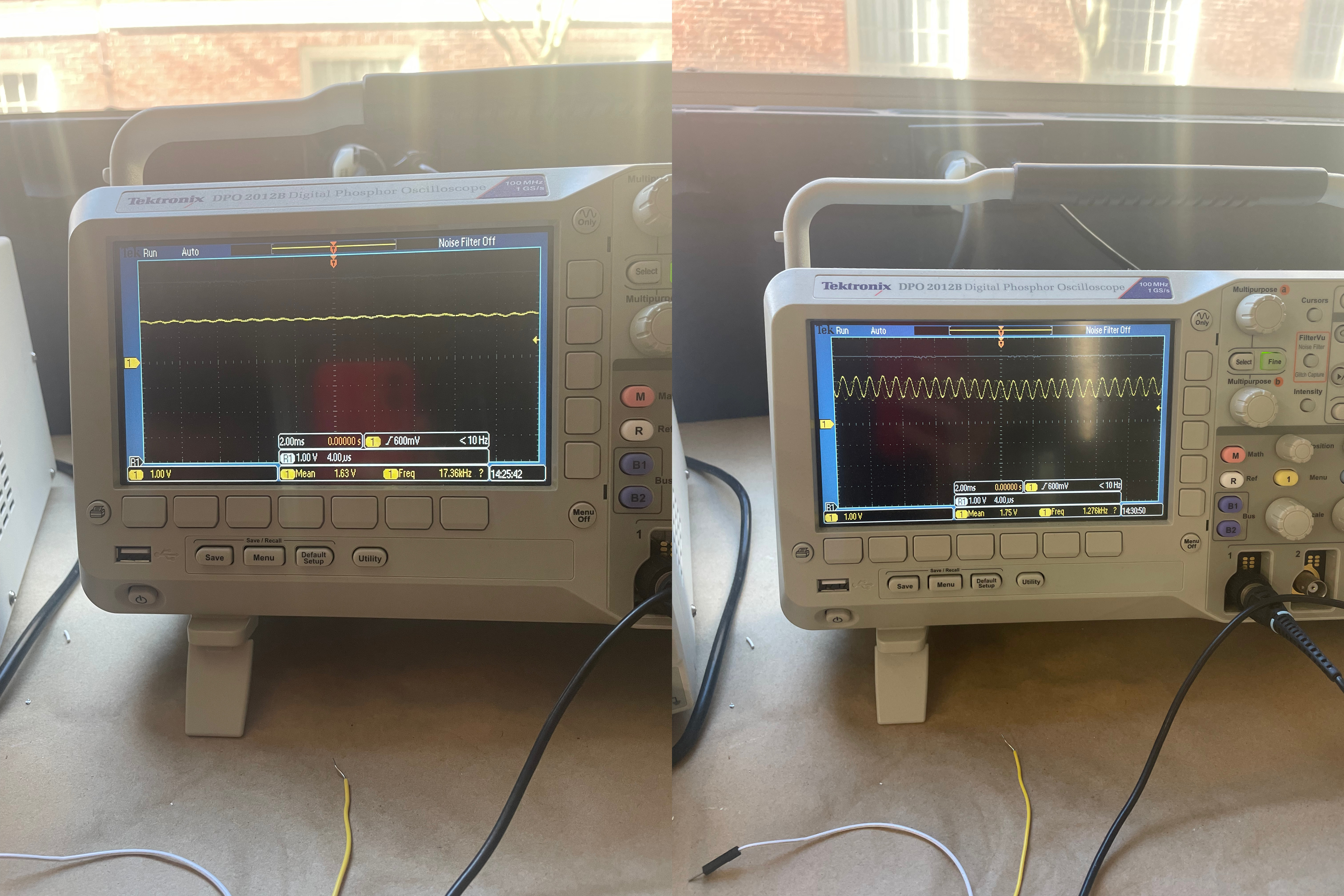
I managed to create an op-amp circuit for the SPW2430 to amplify the signal. Here’s an oscilloscope reading of the amplified output and the PNG. The amplified readings are clipped (the top is cut off) since the op-amp is not rail-to-rail, but the peak-to-peak voltage is now ~0.5V which is enough to be picked up by the ESP32 ADC.
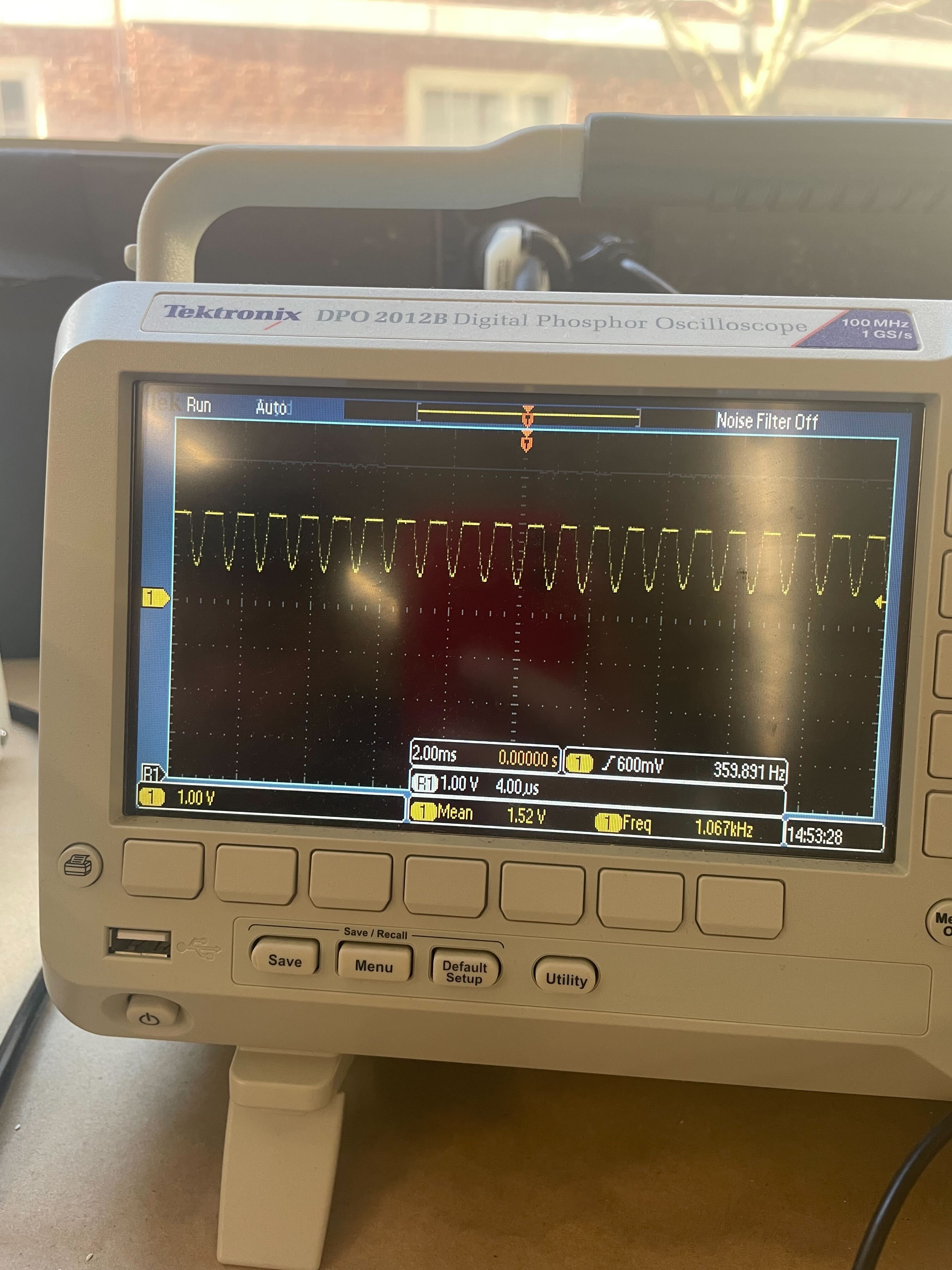
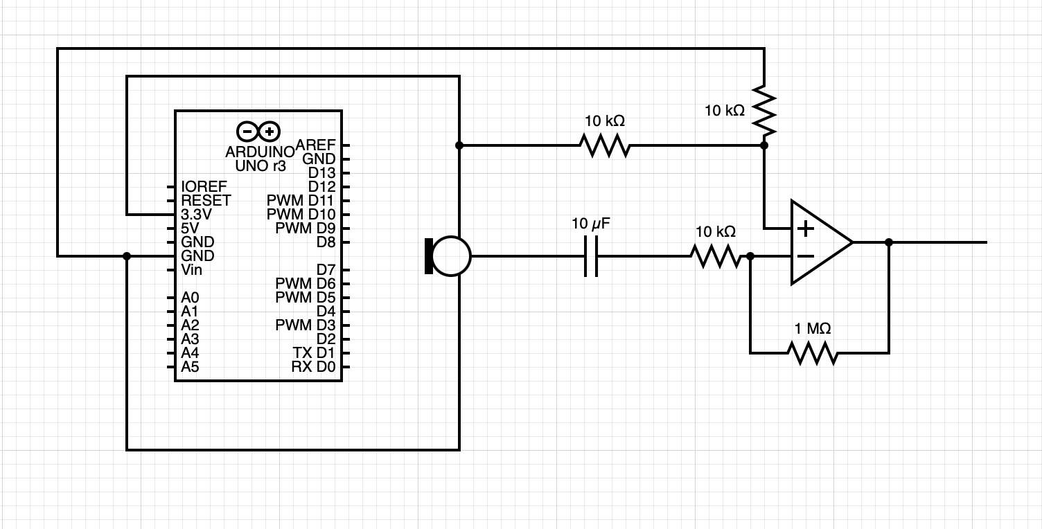
The left is unamplified and the right is amplified
SPH0645 I2S Mic
There were some tutorial on how to hook-up this microphone, however after spending an hour and abit, I could not get this to read anything apart from 0 with two different chips. I gave up on this one and moved onto the next one.
INMP441 I2S Mic
This is the last type of microphone that the lab stocked, Google says it’s similar to the SPH0645 I2S Mic and also wired up similarly. All the tutorials online are for the ESP32 which have different GPIO pins than the ESP32S2 Dev Kit, I found that the corresponding pins that gave me a signal are:
| ESP32 Pin | INMP441 Pin | ESP32S2 Pin |
|---|---|---|
| 3.3V | VCC | 3.3V |
| GND | GND | GND |
| 25 | WS | 15 |
| 33 | SD | 17 |
| 32 | SCK | 16 |
I followed the tutorial on this website https://dronebotworkshop.com/esp32-i2s/ to get microphone to output a signal, albeit a wrong signal.
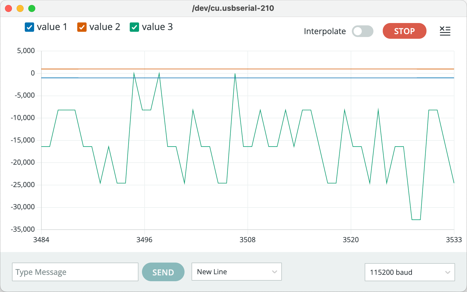
The tutorial shows that the signal should be positive, and usually range between -3000 to 3000, but my signal was negative. I tried to figure out why, and stumbled upon this single stackechange post
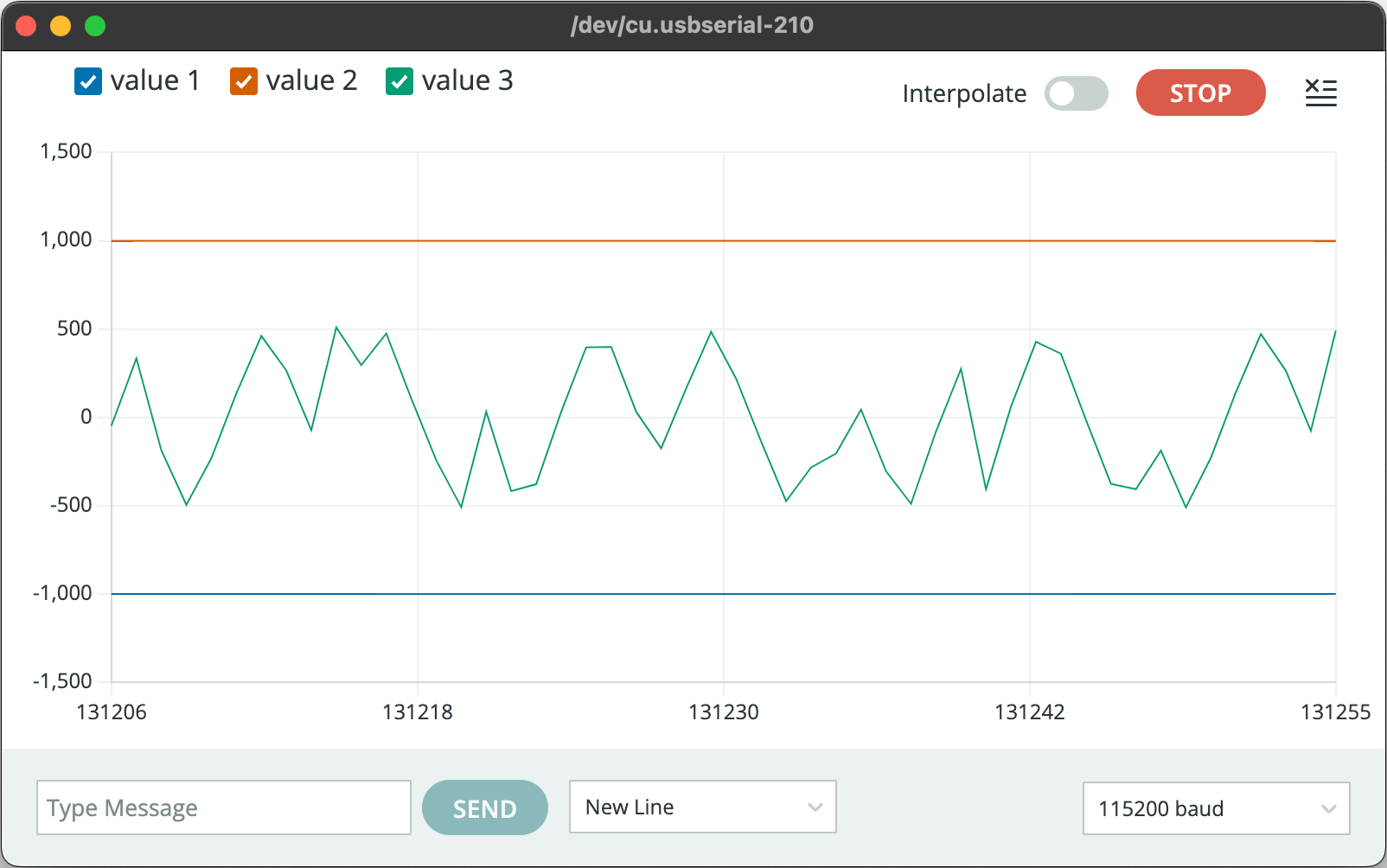
made in Dec. 2022 explaining that for IDF V4.4.3 (the ESP32 firmware) there appears to be a bug with regards to the left and right channel selection. Therefore, changing one line of code in the example, from
.channel_format = I2S_CHANNEL_FMT_ONLY_LEFT
to
.channel_format = I2S_CHANNEL_FMT_ONLY_RIGHT fixed the issue.
After writing some code with the help of some boilerplate templates, I was able to record a .wav file onto the internal SPIFFS memory. I then used the arduino fileserver example code to download the .wav file onto my system.
Getting the speaker to work
The next step is to get the speaker to play an audio recorded by the microphone. The first step was to play a .wav file following this tutorial
, however I didn’t end up getting it working. I suspect that there is an issue with the library since I was able to play tones using the arduino tones function out of the speaker, just not the example wav file from the library.
After being satisfied that there was no easy fix to play .wav files from the speaker, I gave up on the idea of playing back audio from the speaker.
Idea 2: Speech-to-text
My second idea was to use the microphone to record speech and then convert the speech to text using some kind of web-server (for the purposes of this assignment, I am generously assuming that a web-server and raspberry pi counts as an output device).
Since I already had a .wav file saved onto the internal ESP32 memory, all that’s left to do is figure out how to upload that file to a locally hosted web-server. For this, we can use the Wifi library to connect to the MAKERSPACE wifi network and then use the HTTPClient library to upload to the a locally hosted web-server on my computer/pi. The code for this is as follows:
// Connect to WiFi
void wifiConnect(void *pvParameters){
  isWIFIConnected = false;
  char* ssid = "MAKERSPACE";
  char* password = "12345678";

  WiFi.begin(ssid, password);
  while(WiFi.status() != WL_CONNECTED){
    vTaskDelay(500);
    Serial.print(".");
  }
  isWIFIConnected = true;
  while(true){
    vTaskDelay(1000);
  }
}

// Upload file to ip_address:port
void uploadFile(){
  file = SPIFFS.open(filename, FILE_READ);
  if(!file){
    Serial.println("FILE IS NOT AVAILABLE!");
    return;
  }

  Serial.println("===> Upload FILE to Node.js Server");

  HTTPClient client;
  client.begin("http://192.168.0.117:8888/uploadAudio");
  client.addHeader("Content-Type", "audio/wav");
  int httpResponseCode = client.sendRequest("POST", &file, file.size());
  Serial.print("httpResponseCode : ");
  Serial.println(httpResponseCode);

  if(httpResponseCode == 200){
    String response = client.getString();
    Serial.println("==================== Transcription ====================");
    // writer(response);
    Serial.println(response);
    Serial.println("====================      End      ====================");
  }else{
    Serial.println("Error");
  }
  file.close();
  client.end();
}
The web-server code is written in javascript, and is based off this 5 part tutorial . It currently uses Google’s Text-to-Speech API, but I plan to replace it with a local TTS engine run natively on the Pi using Whisper.
var fs = require("file-system");
const http = require("http");
const server = http.createServer();
const fileName = "./resources/recording.wav";
server.on("request", (request, response) => {
if (request.method == "POST" && request.url === "/uploadAudio") {
var recordingFile = fs.createWriteStream(fileName, { encoding: "utf8" });
request.on("data", function(data) {
recordingFile.write(data);
});
request.on("end", async function() {
recordingFile.end();
const transciption = await speechToTextAPI();
response.writeHead(200, { "Content-Type": "text/plain" });
response.end(transciption);
});
} else {
console.log("Error Check your POST request");
response.writeHead(405, { "Content-Type": "text/plain" });
}
});
async function speechToTextAPI() {
// Imports the Google Cloud client library
const speech = require("@google-cloud/speech");
const fs = require("fs");
// Creates a client
const client = new speech.SpeechClient();
// Reads a local audio file and converts it to base64
const file = fs.readFileSync(fileName);
const audioBytes = file.toString("base64");
// The audio file's encoding, sample rate in hertz, and BCP-47 language code
const audio = {
content: audioBytes
};
const config = {
encoding: "LINEAR16",
sampleRateHertz: 16000,
languageCode: "en-US"
};
const request = {
audio: audio,
config: config
};
// Detects speech in the audio file
const [response] = await client.recognize(request);
const transcription = response.results.map((result) => result.alternatives[0].transcript).join("\n");
console.log(`Transcription: ${transcription}`);
return transcription;
}
const port = 8888;
server.listen(port);
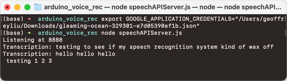
console.log(`Listening at ${port}`);
The quality of the sound recording isn’t terrible and TTS works quite well but could be improved with a better mic and TTS system. Here’s some examples of my text-to-speech system in action:
A summary of the system:
- ESP32S2 records audio off INMP441 I2S microphone
- Saves recording as a
.wavfile onto internal SPIFF memory - Sends
.wavfile to a locally hosted web-server - Web-server sends a compressed file to Google’s Speech-to-Text API to convert audio to text
- Web-server sends converted text back to arduino.
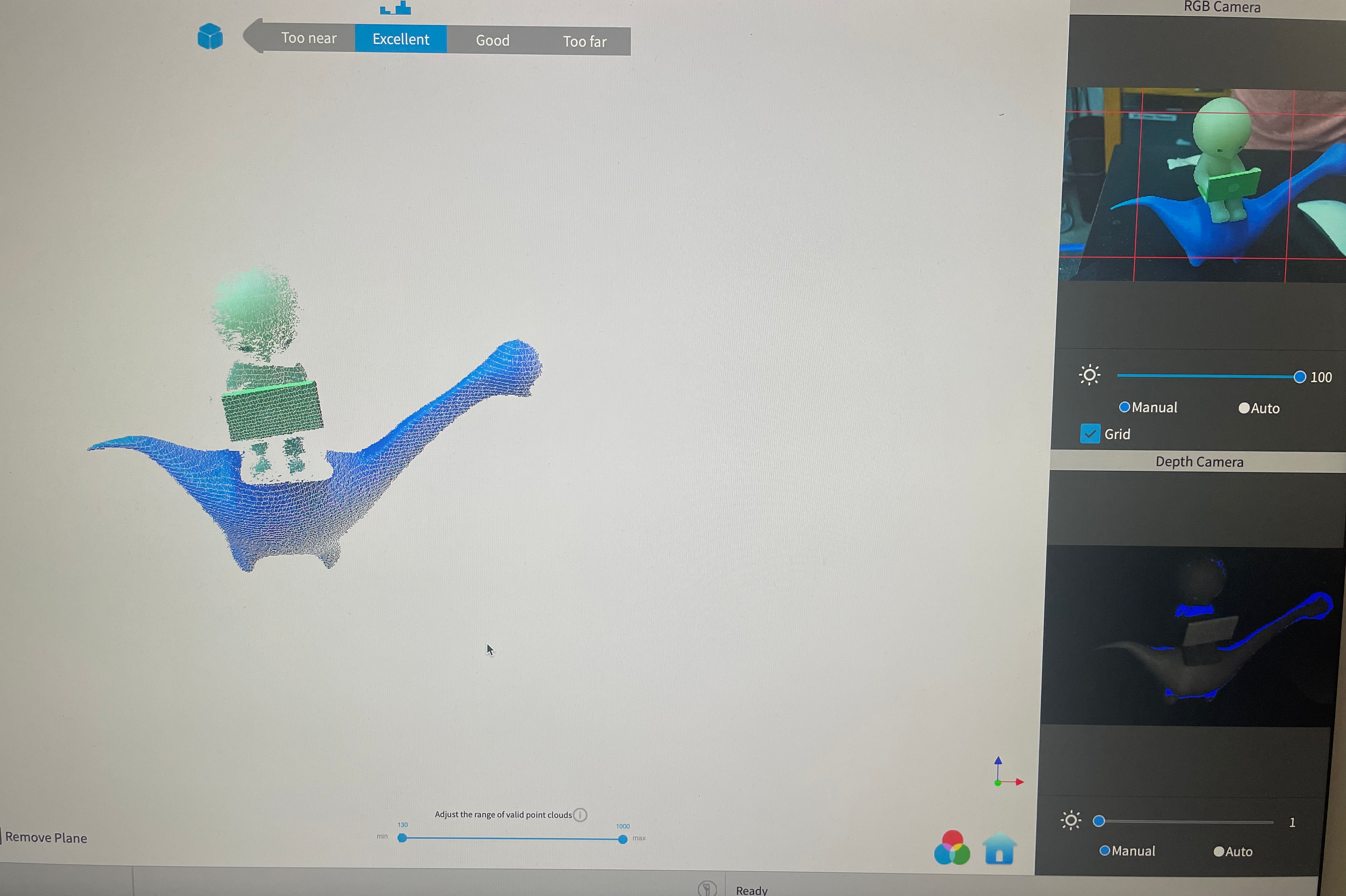
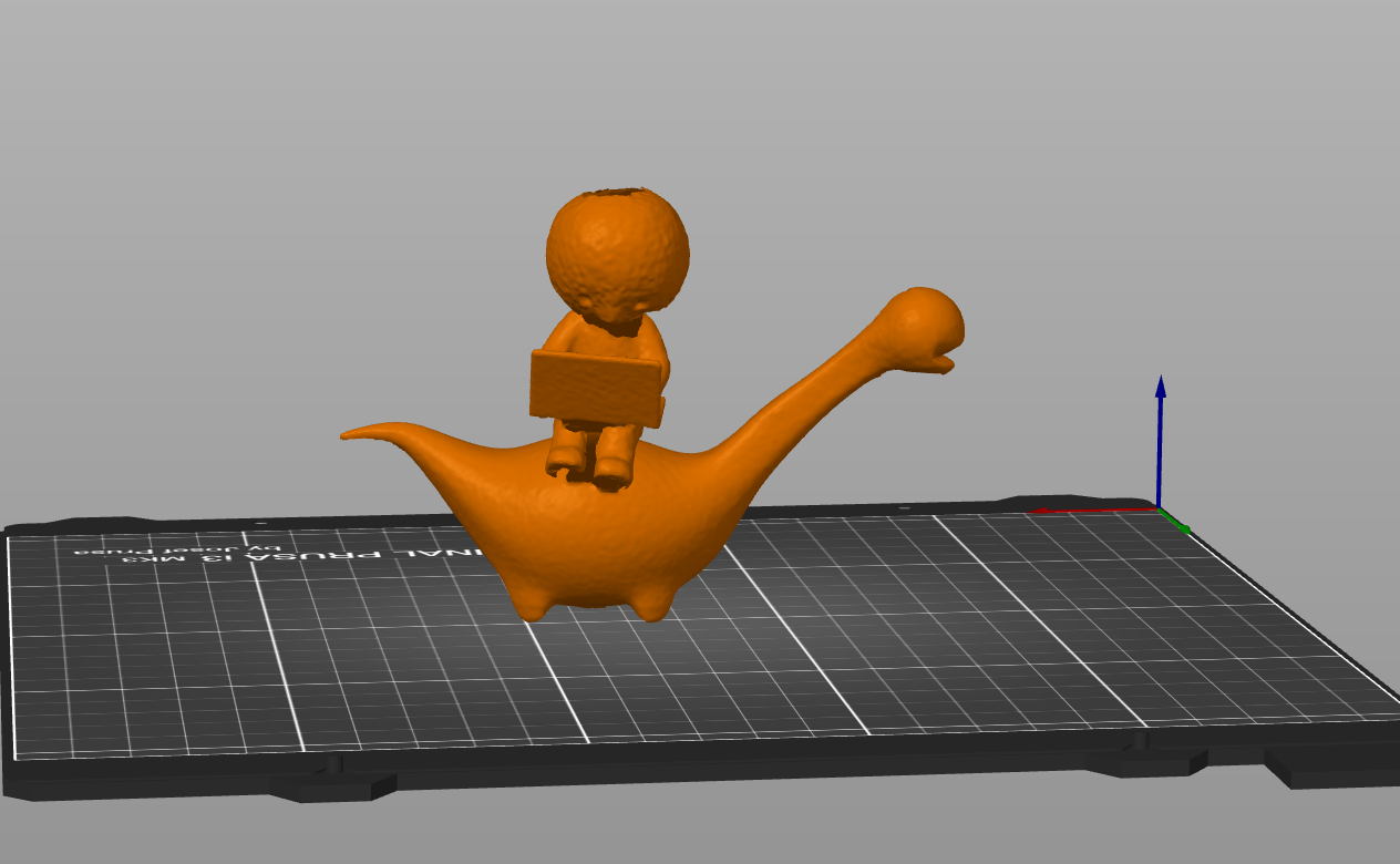
Revopoint makeup
I used the revopoint scanner to scan a little 3D figurine that I borrowed from Ashley. It took 3-4 scans to get a nice output. I’ve attached a picture of the revopoint software, a picture of the final STL file and also the STL file itself.