Week 6: Electronic Input Devices
Table of contents
We covered various types of capacitive sensors this week, I use charged copper sheets to create my own water-level sensor and also tacked 3D positoning using an the MPU6050.
Items
- MPU6050 (or another 6-9 axis IMU)
- Breadboard
- ESP32
- Wires
3D positioning with the MPU6050
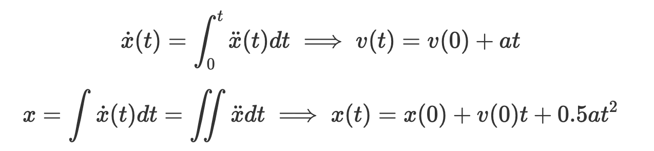
At the start of the week, I thought a great idea would be to get a 3D positioning. The idea is that I could use the acceleration and gyroscope readings from the MPU6050, apply some fancy filters and data-processing to somehow get a more accurate reading, and double-integrate the processed acceleration values to obtain the 3D displacement.
$$\dot{x}(t) = \int_0^t \ddot{x}(t) dt \implies v(t) = v(0) + at$$
$$x = \int \dot{x}(t) dt = \int \int \ddot{x} dt \implies x(t) = x(0) + v(0)t + 0.5at^2$$
Calibration
To calibrate the sensor, we first need to know how the gyro and accelerometer work. The accelerometer reads the force on a small mass relative to its own rest frame, so a stationary accelerometer should read 1G (9.81m/s) in the z-direction and 0G in the x and y directions. In free-fall, it would read 0G’s in all directions. The gyro reads the angular velocity of the sensor, so a stationary gyro should read 0 in all directions. The accelerometer provides an absolute measurement (not relative to an initial value) while the gyroscope is a relative measurement (measurement is relative to an initial value).
Adafruit MPU6050 Library
The first thing we need to do is calibrate the sensor. This is because the sensor is not perfect, and will have some offset in the readings when stationary. There wasn’t really a best-practice for calibrating the sensor. The Adafruit library examples output numbers in $m/s^2$ for the accelerometer and $rad/s$ for the gyroscope. We can do this by taking the average of the readings over a period of time, and subtracting that from the readings.
Offsets
AccelX:0.54
AccelY:0.24
AccelZ:10.24
GyroX:-0.04
GyroY:0.17
GyroZ:0.46
Laying the sensor flat on a table, we can see that the accelerometer reads $10.24m/s^2$ in the z-direction, and $0.54m/s^2$ in the x-direction and $0.24m/s^2$ in the y-direction. The gyroscope reads 0.46rad/s in the z-direction, and 0.17rad/s in the y-direction and -0.04rad/s in the x-direction. This is a good start, but we can do better.
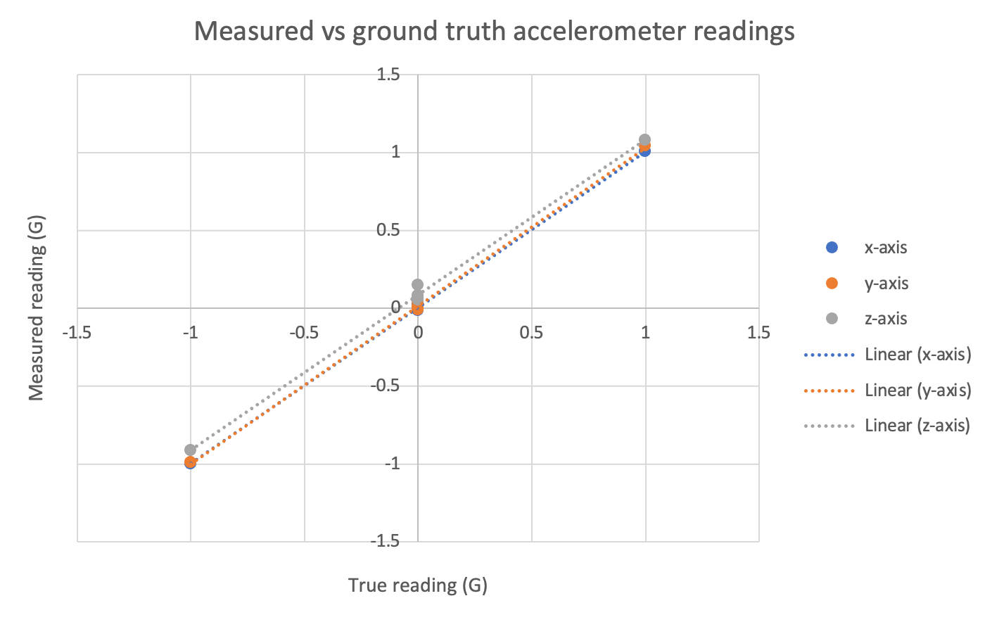
We can also calibrate the sensor by using gravity as a reference for all 6 sides of the sensor. If the sensor is perfectly linear, then we should expect that the accelerometer also reads $-10.24m/s^2$ in the z-direction if it is flipped over by 180 degrees along the $x$ or $y$ axis. We can also repeat this for the X and Y axes. After doing this, it does not seem like the sensor is linear, furthermore the axes don’t appear to be independent (however I have to give the sensor the benefit of the doubt because when doing the tests my level reference may not truly be perpendicular to gravity). The gyroscope appears to give consistent offsets when the sensor isn’t moving which is a good sign.
Offsets
AccelX:0.54
AccelY:0.24
AccelZ:10.24
GyroX:-0.04
GyroY:0.17
GyroZ:0.46

AccelX:1.48
AccelY:0.10
AccelZ:-9.69
GyroX:-0.04
GyroY:0.17
GyroZ:0.46

Offsets
AccelX:0.70
AccelY:-9.78
AccelZ:-0.06
GyroX:-0.04
GyroY:0.17
GyroZ:0.46

Offsets
AccelX:0.80
AccelY:9.87
AccelZ:0.08
GyroX:-0.04
GyroY:0.17
GyroZ:0.46

Offsets
AccelX:10.62
AccelY:-0.01
AccelZ:0.39
GyroX:-0.04
GyroY:0.16
GyroZ:0.46

Offsets
AccelX:-8.93
AccelY:-0.14
AccelZ:-0.10
GyroX:-0.04
GyroY:0.17
GyroZ:0.46
Code for calibration
// Basic demo for accelerometer readings from Adafruit MPU6050

#include <Adafruit_MPU6050.h>
#include <Adafruit_Sensor.h>
#include <Wire.h>

Adafruit_MPU6050 mpu;

void setup(void) {
  Wire.begin(16, 17);
  Serial.begin(115200);
  while (!Serial) {
    delay(10); // will pause Zero, Leonardo, etc until serial console opens
  }

  // Try to initialize!
  if (!mpu.begin()) {
    Serial.println("Failed to find MPU6050 chip");
    while (1) {
      delay(10);
    }
  }

  mpu.setAccelerometerRange(MPU6050_RANGE_16_G);
  mpu.setGyroRange(MPU6050_RANGE_250_DEG);
  mpu.setFilterBandwidth(MPU6050_BAND_21_HZ);
  Serial.println("");
  delay(100);
}


void Update(){
  float ax = 0;
  float ay = 0;
  float az = 0;
  float gx = 0;
  float gy = 0;
  float gz = 0;
  float currentMicros = micros();
  float n = 0;
  while(n<1000){

    if (micros() - currentMicros > 100){ // Get less correlated readings
      sensors_event_t a, g, temp;
      mpu.getEvent(&a, &g, &temp);
      ax += a.acceleration.x;
      ay += a.acceleration.y;
      az += a.acceleration.z;

      gx += g.gyro.x;
      gy += g.gyro.y;
      gz += g.gyro.z;

      currentMicros = micros();
      n += 1;
    }
  }
  ax = ax/1000;
  ay = ay/1000;
  az = az/1000;
  gx = gx/1000;
  gy = gy/1000;
  gz = gz/1000;

  Serial.println("Offsets");
  Serial.print("AccelX:");
  Serial.println(ax);
  Serial.print("AccelY:");
  Serial.println(ay);
  Serial.print("AccelZ:");
  Serial.println(az);

  Serial.print("GyroX:");
  Serial.println(gx);
  Serial.print("GyroY:");
  Serial.println(gy);
  Serial.print("GyroZ:");
  Serial.println(gz);
}

void loop() {

  /* Get new sensor events with the readings */
  Update();
}
Electronic Cats library
The Adafruit library is quite limiting in that it’s not really easy to decipher what goes on in the background, so after calibrating using the Adafruit library, I decided to try out the Electronic Cats library. The Electronic Cats library is much more flexible, it allows you to read raw values and also has functions that allow you to specify your sensor offsets. However, they only allow single offset values for each axis and thus don’t allow for non-linear calibration. One of the major benefits of the Electronic Cats library is accessing the Digital Motion Processor (DMP) (which will be explained below).
Sensor fusion
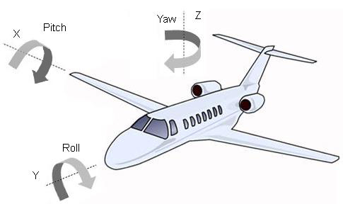
Sensor fusion is the process of combining multiple sensors to get a more accurate reading. In our case, we are able to use the accelerometer readings to get a more accurate rotational reading compared to only relying on the gyroscope. The idea is that we integrate the gyroscope (since it is a relative measure) to get the change in orientation of the sensor. We can also use the acceleration readings to get a noisy absolute measure of orientation by assuming that total acceleration magnitude is 1G (when stationary) to obtain partial orientation information (pitch and roll, however yaw is unidentifiable through accelerometer readings). These calculations are relatively complex and I won’t explain them here but it is well documented in this blog post . There are many filters that you could use here, Kalman (plus extended variants) as well as Madgwick (plus extensions) are popular.
Coming back to the DMP… the electronic cats library allows us to access the DMP which does all this sensor fusion for us. After doing some research, there are some pros and cons to relying on the DMP.
Con: It appears that the DMP on the MPU6050 uses a proprietary algorithm, and source code isn’t available to understand how the sensors are combined. It is not the most accurate sensor-fusion algorithm out there. Pro: Sensor fusion processing can be quite costly, especially if many sensors are used with a single micro-controller. The DMP takes all sensor-fusion calculations off the microprocessor, freeing up processing power for other stuff.
Orientation & 3D positioning
After calibration, we can extract the orientation and approximate 3D position by reading from the DMP and double integration of the acceleration values, however this isn’t particularly straight forward. Since I ran out of time in this weeks documentation and this section isn’t technically part of the assignment requirements, I will aim to complete this later.
Self-fabricated water-level sensor
Materials
- Copper sheet
- Plastic cup (with volumetric markings, or scale if using unmarked cup)
- Alligator clips
- 2x10MOhm sensor
Using the copper sheets, I made my own capacitative water-level sensor. The schematic and a picture of the sensor is shown below.
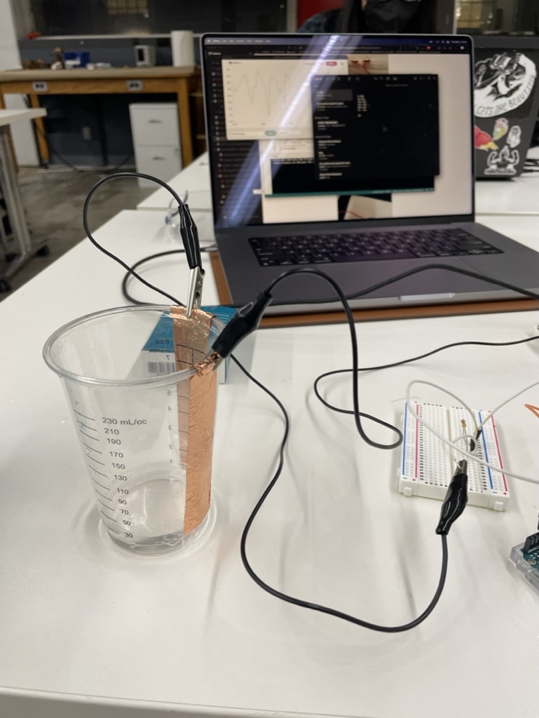
The sensor works by using the difference in conductivity of water and air, and the capacitance of the copper sheets. Then by using transmit-receive (TX-RX) capacitive sensing, we can measure the change in conductivity as the air is displaced with liquid. Our readings should increase as the water level increases.
Circuit schematic
I used a standard TX-RX circuit schematic which is shown here. Take careful note that at a wire cross-section joined wires are marked with a solid black dot, and unjoined wires do not have a solid dot (see here )

Calibration
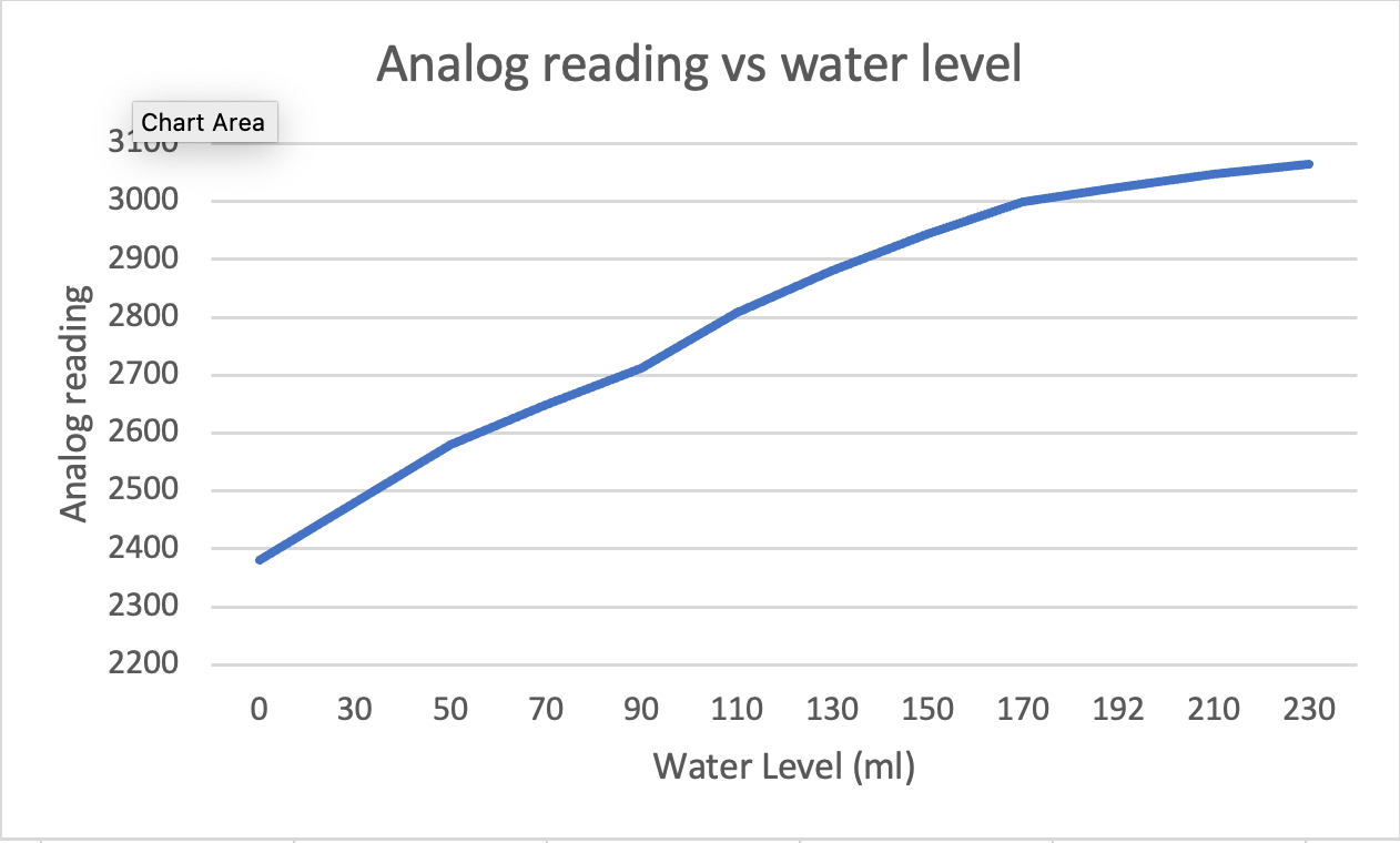
To calibrate the sensor, I found a plastic cup with milliliter measurement markings on the side, this allowed me to easily calibrate my water-level sensor since I can take an analogue reading. I wrote some code to take an average of 10,000 readings and prints it out to the serial monitor when a button is pressed. To calibrate the sensor, all I had to do was fill up the cup with different water levels, press the button and record the reading and repeat. This allowed for minimal ambiguity in how to read the sensor value. There appears to be a logarithmic relationship between the water level and the sensor readings.
Code
const int buttonPin = 1;
int buttonState = 0;
int timer = 0;
int data = 0;
int already_read = 0;

// Define capacitor class

class Capacitor{
  int tx_pin;  //Top capacitor plate
  int rx_pin;  //Bottom capacitor plate
  int high_read; //Read when top plate is charging
  int low_read; //Read the resulting discharge of the top plate
  int N_samples = 1000;
  int diff;  //Find the difference between the reading the bottom plate gets when the top plate is charging and then discharges to get the result
  long result;
  int tx_state; //Is the top plate charging?
  unsigned long previousMicros;
  long capTime; //How long I want the top plate to charge

  public:
  Capacitor(int tp, int rp, int interval){  //Declare inputs into my class
    tx_pin = tp;
    rx_pin = rp;
    capTime = interval;
    previousMicros = 0;

    pinMode(tx_pin, OUTPUT);
  }
  long Update()
  {
    unsigned long currentMicros = micros(); //Get current time
    result = 0; //Reset the result
    //Read N samples and take the sum of the readings
    for(int i = 0; i<N_samples; i++){
      currentMicros = micros();
      //Charge the top plate
      digitalWrite(tx_pin,HIGH);
      tx_state = HIGH;
      high_read = analogRead(rx_pin); //See what the bottom plate is reading

      //Time charging the tx plate
      if((tx_state == HIGH) && (currentMicros - previousMicros >= capTime)){ //If the top plate has been charging and it is now time to discharge
        previousMicros = currentMicros;
        digitalWrite(tx_pin,LOW);
        tx_state = LOW;
        low_read = analogRead(rx_pin); //See what the bottom plate is reading now
        diff = high_read - low_read;
        result += diff;
      }
    }
    return result;
  }

};
Capacitor cap1(4,A3,1000); //TX on Pin 4, RX on Pin A3, charge the top plate for 100 microseconds

void setup() {
  // put your setup code here, to run once:
  Serial.begin(9600);
}

void loop() {
  // put your main code here, to run repeatedly:

  buttonState = digitalRead(buttonPin);
  digitalWrite(LED_BUILTIN, LOW);
  // Serial.println(buttonState);
  Serial.println('Waiting for values');
  while(buttonState == LOW){
    buttonState = digitalRead(buttonPin);
    if (micros() - timer > 1000000){
      Serial.print(".");
      timer = micros();
    }
  }
  already_read = 0;
  while (buttonState == HIGH){
    buttonState = digitalRead(buttonPin);
    if (already_read == 0){
      Serial.println("Reading values");
      digitalWrite(LED_BUILTIN, HIGH);
      data = cap1.Update();
      Serial.println(data);
      already_read = 1;
    }

  }

  Serial.println("Press button for next reading");
  while(buttonState == LOW){
    buttonState = digitalRead(buttonPin);
    if (micros() - timer > 1000000){
      Serial.print(".");
      timer = micros();
    }
  }

}