Sidewalk Plotter (Team Thursday)
Table of contents
Week 10: Machine Building
This week we worked in a group project to build a “sidewalk plotter” with the following evaluation criteria:
- Ability to calibrate motor position (i.e. guarantee the “home” position is the sam each time you power on the device)
- Novelty of the end-effector / drawing technique
- Precision: ability to draw a 1m-diameter circle and mark its center point
- Complexity of drawing output
Materials
- Chassis
- 1 12x24" sheet of 1/8" plywood
- 2x 80mm wheels
- 2 3D printed wheel mounts
- 2 3D printed stepper motor housing attachment
- 1 caster wheel
- M3 hex screws
- 1/4" square dowel (1 feet total)
- Electronics
- 2 Stepper Motors
- 1 MPU6050 IMU
- 1 Power Bank
- 2 Low Voltage Motor Drivers
- End effector
- 1 5V 2-Channel Module with Optocoupler
- 1 mini air pump + tubing
- 1 plastic container for water
Design choices
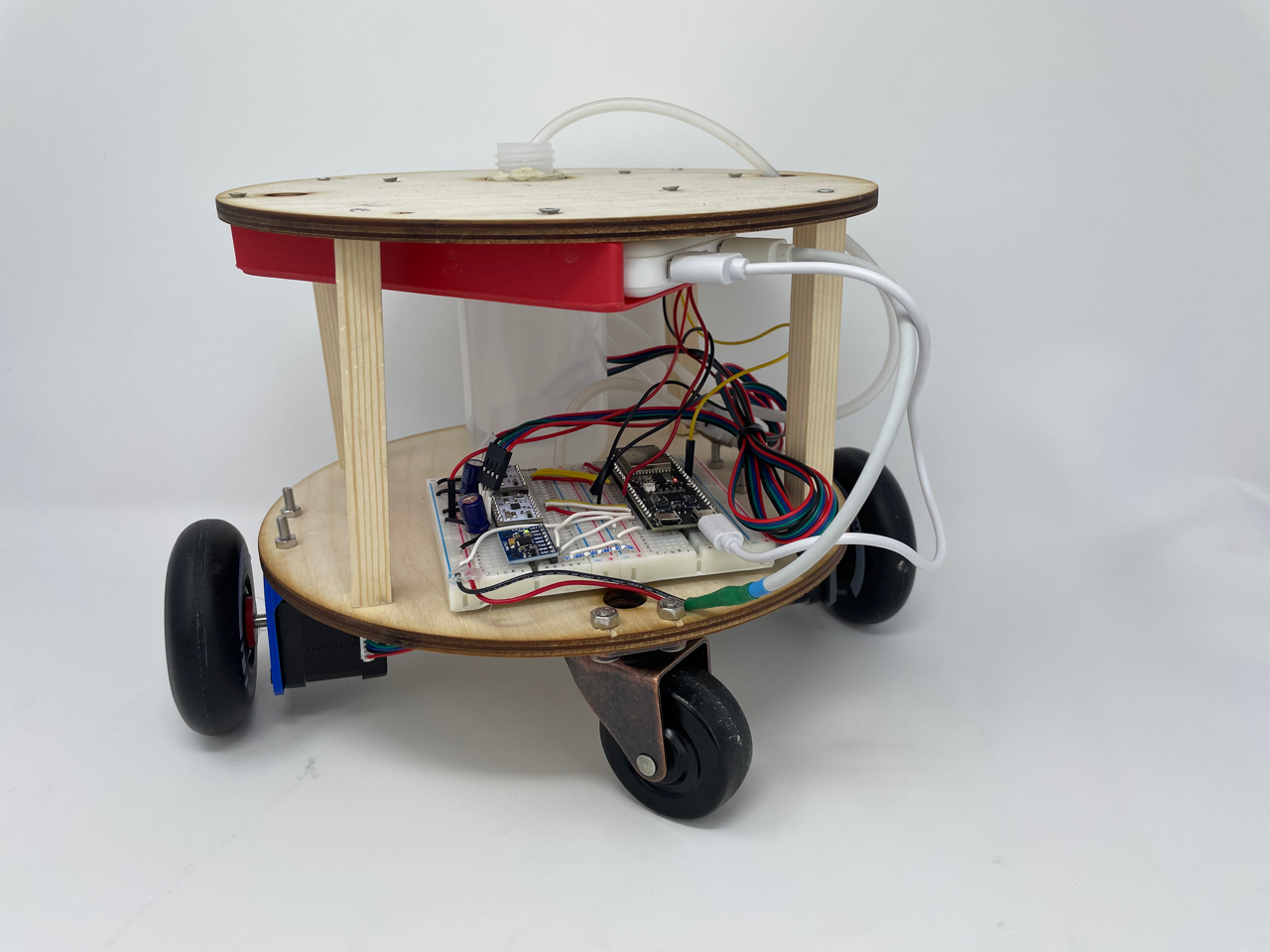
Since one of the criterion was to draw a 1 meter diameter circle, we did not want to make a drawing robot that was 1m long. We wanted to design a robot that was able to draw large scale images, but also compact enough to carry around. We started with the overall design and were inspired by the mobility of a Roomba . The design was meant to be compact so we opted for a round double-decker shape, where the electronics would exist on one level and other components such as the water container and the battery can exist on the other level.
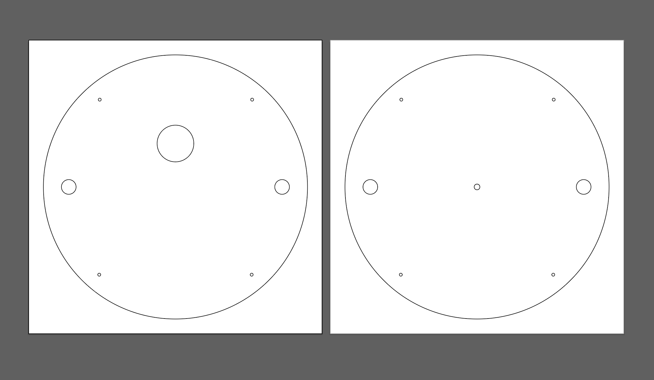
Chassis
The top and bottom layers were laser cut into quarter inch thick wood. The four corner holes were used for aligning the posts that separated and support the two layers. Holes for the motor cords for the water storage device and its tube allow for access to power and the liquid for the “drawing” requirement across layers. The stepper motors were attached to the main body with a 3D printed part that was found on Thingiverse and then held in place with screws. We also designed a 3D printed attachment to directly attach the 80mm wheels to the D shaped stepper motor shafts.
Software and Electronics
On the software end, there were two main parts to the code:
- creating the website that would translate user input into recognizable commands
- programming the robot to interpret and follow those commands.
Website for User Input
For user input, we wanted people to be able to draw whatever they wanted, so we had a site with a coordinate plane where they could either draw or press a button to draw a circle. To accomplish this, we use the React-p5 library to create an interactive canvas that people could draw on:
Web app code (Click to reveal code)
export default function Canvas(props) {

    const setup = (p5, canvasParentRef) => {
        p5.createCanvas(props.width, props.height).parent(canvasParentRef)
    }

    const mp = (e) => {
        if (e.mouseY > 620 || e.mouseY < 0 || e.mouseX > 1080 || e.mouseX < 0) {
            return;
        }
        mouseX = e.mouseX;
        mouseY = e.mouseY;
        props.x_coordinates.push(mouseX);
        props.y_coordinates.push(mouseY);
        props.pen.push(1);
    }

    const draw = (p5) => {
        if (props.clear) {
            p5.clear();
            props.clearHandler();
            mouseX=0;
            mouseY=0;
            pmouseX=0;
            pmouseY=0;
        }
        p5.background(255, 0);
        p5.line(mouseX, mouseY, pmouseX, pmouseY);
        pmouseX = mouseX;
        pmouseY = mouseY;
    };

    return <Sketch setup={setup} draw={draw} mousePressed={mp} />;
};
We then embedded this within a site built on React. Using event handlers and the Javascript Fetch API, the site records a list of coordinates where the user has clicked and sends them to the API when the appropriate button is clicked:
Web API Code (Click to reveal code)
function App() {
  const [clear, setClear] = useState(false);
  let array1 = [];
  let array2 = [];
  let array3 = [];

  const clearHandler = () => {
    setClear(false);
  }

  const handleClick = (circle) => {
    setClear(true);
    let today = new Date(),
      time = today.getHours() + ':' + today.getMinutes() + ':' + today.getSeconds();
    let jsonData;

    if (circle) {
      jsonData = {
        "x_coordinates": array1,
        "y_coordinates": array2,
        "pen": array3,
        "time": time,
        "circle": true
      }
    } else {
      jsonData = {
        "x_coordinates": array1,
        "y_coordinates": array2,
        "pen": array3,
        "time": time,
        "circle": false
      }

    }
    jsonData = JSON.stringify(jsonData);
    console.log(jsonData);
    fetch('https://ps70-api.vercel.app/', {
      method: 'POST',
      mode: 'cors',
      headers: {
        'Accept': 'application/json',
        'Content-Type': 'application/json'
      },
      body: jsonData
    })
      .then(response => console.log(response))
  }

  return (
    <div class="App">
      <h1>PS70 Sidewalk Plotter App</h1>
      <h3>Draw what you want to create below!</h3>
      <div class="container">
        <img src="https://img.freepik.com/free-vector/abstract-horizontal-grid-lines-graph-style-graphic-design_1017-39918.jpg?w=1080" alt="Grid" />
        <Canvas width="1080" height="600" x_coordinates={array1} y_coordinates={array2} pen={array3} clear={clear} clearHandler={clearHandler} />
      </div>
      <button class="button-green" onClick={() => handleClick(false)}>Send to Plotter</button>
      <button class="button-blue" onClick={() => handleClick(true)}>Draw Circle ⚪</button>
      <button class="button-red" onClick={() => setClear(true)}>Clear</button>
    </div>
  );
}

export default App;
Feel free to check out what the final site looks like here!
That would send a set of coordinates to an API, which we then had to convert into instructions for the robot in the form “turn x degrees, then move y centimeters.” We did this through some fun geometry and two classes:
Co-ordinate processing (Click to reveal code)
class Point {
  constructor(ls) {
    this.x = ls[0];
    this.y = ls[1];
  }

  distance(other) {
    /*
      * Gets distance between current point and new point
      */
    return Math.sqrt(Math.pow(this.x - other.x, 2) + Math.pow(this.y - other.y, 2));
  }

  angle(other) {
    /*
      * Gets angle between current point and new point
      * If facing east, how many degrees to turn counterclockwise to face new point
      */
    if (this.x === other.x) {
      return (this.y < other.y ? 90 : 270);
    }
    const slope = (this.y - other.y) / (this.x - other.x)
    const angle = Math.atan(slope) * (180 / Math.PI);
    if (this.x > other.x) {
      return 180 + angle;
    } else {
      return 360 + angle;
    }
  }

  toString() {
    return `(${this.x}, ${this.y})`;
  }
}

module.exports = Point;
class Robot {
  constructor() {
    this.position = new Point([0, 0]);
    this.angle = 0;
  }

  get_distance(coordinate) {
    /*
      * Gets distance robot needs to travel
      */
    return this.position.distance(coordinate);
  }

  get_angle(coordinate) {
    /*
      * Gets angle between current angle and new angle to turn to
      * adjusts this to be between -180 and 180 to avoid unnecessary turns
      */
    const angle = (this.position.angle(coordinate) - this.angle) % 360;
    if (Math.abs(angle) < 180) {
      return angle;
    } else if (angle < 0) {
      return 360 + angle;
    } else {
      return angle - 360;
    }
  }

  moveto(coordinate) {
    /*
      * Updates robot's position and angle to new values
      * Returns the command
      */
    const angle_change = this.get_angle(coordinate);
    const distance_change = this.get_distance(coordinate);
    this.position = coordinate;
    this.angle = this.angle + angle_change;
    return {
      angle: angle_change,
      distance: distance_change
    }
  }

  generateInstructions(coordinates) {
    const instructions = []
    for (const c of coordinates) {
      let instruct = this.moveto(new Point(c.slice(0, 2)));
      instruct.pendown = c[2];
      instructions.push(instruct);
    }
    return instructions;
  }
}

module.exports = Robot;
const express = require('express');
const cors=require("cors");
const Robot = require('./Robot');

const app = express();
const port = 3000;
let output = {
  instructions: [],
  id: 0
}

let current_gyro = {
  x: 0,
  y: 0,
  z: 0
}

app.use(express.json());

const corsOptions ={
   origin:'*',
   credentials:true,
   optionSuccessStatus:200,
}

function getRandomInt(min, max) {
  min = Math.ceil(min);
  max = Math.floor(max);
  return Math.floor(Math.random() * (max - min + 1)) + min;
}

app.use(cors(corsOptions))

app.post('/gyro', (req, res) => {
  let euler_x = req.body.euler_x * 180 / Math.PI;
  let euler_y = req.body.euler_y * 180 / Math.PI;
  let euler_z = req.body.euler_z * 180 / Math.PI;
  current_gyro = {
    x: euler_x,
    y: euler_y,
    z: euler_z,
  }
  res.send(`Set gyro to ${current_gyro}`);
});

app.get('/gyro', (req, res) => {
  res.send(current_gyro);
});

app.get('/', (req, res) => {
  res.send(output);
})

app.post('/', (req, res) => {
  console.log(req.body);
  const xdata = req.body.x_coordinates;
  const ydata = req.body.y_coordinates;
  const pen = req.body.pen;
  //const time = req.body.time;
  let coordinates = [];
  for (let i = 0; i < xdata.length; i++) {
    coordinates.push([xdata[i] * 2, ydata[i] * 2, pen[i]]);
  }
  const robbo = new Robot();
  const instructions = robbo.generateInstructions(coordinates);
  let t = getRandomInt(0, 10000);

  if (req.body.circle) {
    t = t * -1;
    output = {
      instructions: instructions,
      id: t
    }
  } else {
    output = {
      instructions: instructions,
      id: t
    }
  }
  res.send(`Set data to ${output}`);
})

app.listen(port, () => {
  console.log(`API Started On Port ${port}`);
})

module.exports = app;
If you are interested, the final API can be accessed here .
Microcontroller programming
For this part, we split the code into two classes: one that reads data from the gyroscope and one that controls the two stepper motors. The MPU6050 library we used has not been updated in a long time, and we ended up having to modify some of the source files in order to make it its own class, but we eventually got it working:
Microprocessor (Click to reveal code)
Gyro.h:
# ifndef GYRO_H
# define GYRO_H
# include <WiFi.h>
# include <HTTPClient.h>
# include <ArduinoJson.h>
# include <WebServer.h>
# include "helper_3dmath.h"
# include "Wire.h"
# include "I2Cdev.h"
# include "MPU6050_6Axis_MotionApps20.h"

class Gyro
{
  private:
    MPU6050 mpu;
    bool dmpReady;  // set true if DMP init was successful
    uint8_t mpuIntStatus;   // holds actual interrupt status byte from MPU
    uint8_t devStatus;      // return status after each device operation (0 = success, !0 = error)
    uint16_t packetSize;    // expected DMP packet size (default is 42 bytes)
    uint16_t fifoCount;     // count of all bytes currently in FIFO
    uint8_t fifoBuffer[64]; // FIFO storage buffer
    Quaternion q;           // [w, x, y, z]         quaternion container
    VectorInt16 aa;         // [x, y, z]            accel sensor measurements
    VectorInt16 aaReal;     // [x, y, z]            gravity-free accel sensor measurements
    VectorInt16 aaWorld;    // [x, y, z]            world-frame accel sensor measurements
    VectorFloat gravity;    // [x, y, z]            gravity vector
    float euler[3];         // [psi, theta, phi]    Euler angle container
    float ypr[3];           // [yaw, pitch, roll]   yaw/pitch/roll container and gravity vector
    volatile bool mpuInterrupt;
    StaticJsonDocument<250> jsonDocument;
    char buffer[250];
    int interrupt_pin;
    String gyroURL;

  public:
    Gyro(String url);
    static void dmpDataReady();
    void create_json(char *tag, float*value, char *unit);
void add_json_object(char*tag, float value, char *unit);
char*getEuler();
    void gyroSetup();
    void updateGyro();
    void sendGyro();
    float getCurrentAngle();
};

# endif
Gyro.cpp:
# include "Gyro.h"
# include "MPU6050_6Axis_MotionApps20.h"
# include <WiFi.h>
# include <HTTPClient.h>
# include <ArduinoJson.h>
# include <WebServer.h>
# include "I2Cdev.h"
# include "Wire.h"
# define PI 3.1415926535897932384626433832795

Gyro :: Gyro(String url) {
  gyroURL = url;
  dmpReady = false;
  mpuInterrupt = false;
  interrupt_pin = 2;
}
void Gyro :: dmpDataReady() {
  return;
}
void Gyro :: create_json(char *tag, float*value, char *unit) {
  jsonDocument.clear();
  jsonDocument["type"] = tag;
  jsonDocument["euler_x"] = value[0];
  jsonDocument["euler_y"] = value[1];
  jsonDocument["euler_z"] = value[2];
  jsonDocument["unit"] = unit;
  serializeJson(jsonDocument, buffer);
}
void Gyro :: add_json_object(char*tag, float value, char *unit) {
  JsonObject obj = jsonDocument.createNestedObject();
  obj["type"] = tag;
  obj["value"] = value;
  obj["unit"] = unit;
}
char*Gyro :: getEuler() {
  create_json("euler_x", euler, "degrees");
  return buffer;
}

void Gyro :: sendGyro() {
  HTTPClient http;
  // Your Domain name with URL path or IP address with path
  http.begin(gyroURL);
  updateGyro();
  create_json("euler_x", euler, "degrees");
  http.addHeader("Content-Type", "application/json");
  int httpResponseCode = http.POST(buffer);
  http.end();
}

float Gyro :: getCurrentAngle() {
  return euler[0] * 180 / PI;
}

void Gyro :: gyroSetup() {
  Wire.begin(12, 13);
  mpu.initialize();
  pinMode(interrupt_pin, INPUT);
  devStatus = mpu.dmpInitialize();
  mpu.setXGyroOffset(90);
  mpu.setYGyroOffset(44);
  mpu.setZGyroOffset(10);
  mpu.setZAccelOffset(1060); // 1688 factory default for my test chip
  mpu.setXAccelOffset(1491);
  mpu.setYAccelOffset(-5467);
  if (devStatus == 0) {
    // Calibration Time: generate offsets and calibrate our MPU6050
    mpu.CalibrateAccel(10);
    mpu.CalibrateGyro(10);
    mpu.PrintActiveOffsets();
    // turn on the DMP, now that it's ready
    Serial.println(F("Enabling DMP..."));
    mpu.setDMPEnabled(true);
    // enable Arduino interrupt detection
    Serial.print(F("Enabling interrupt detection (Arduino external interrupt "));
    Serial.print(digitalPinToInterrupt(interrupt_pin));
    Serial.println(F(")..."));
    attachInterrupt(digitalPinToInterrupt(interrupt_pin), dmpDataReady, RISING);
    mpuInterrupt = true;
    mpuIntStatus = mpu.getIntStatus();
    // set our DMP Ready flag so the main loop() function knows it's okay to use it
    Serial.println(F("DMP ready! Waiting for first interrupt..."));
    dmpReady = true;
    // get expected DMP packet size for later comparison
    packetSize = mpu.dmpGetFIFOPacketSize();
  } else {
    // ERROR!
    // 1 = initial memory load failed
    // 2 = DMP configuration updates failed
    // (if it's going to break, usually the code will be 1)
    Serial.print(F("DMP Initialization failed (code "));
    Serial.print(devStatus);
    Serial.println(F(")"));
  }
  // setup_task();
  mpu.dmpGetCurrentFIFOPacket(fifoBuffer);
  mpu.dmpGetQuaternion(&q, fifoBuffer);
  mpu.dmpGetEuler(euler, &q);
}
void Gyro :: updateGyro(){
  if (mpu.dmpGetCurrentFIFOPacket(fifoBuffer)){
    mpu.dmpGetQuaternion(&q, fifoBuffer);
    mpu.dmpGetEuler(euler, &q);
  }
}
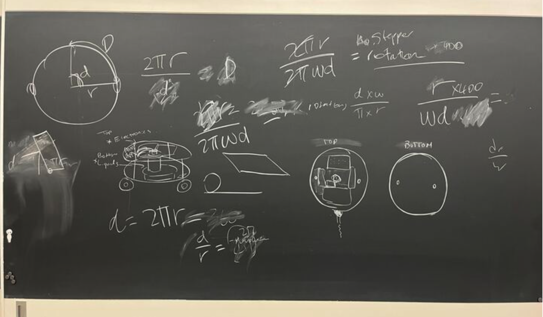
Next, in programming the driving functionality, we took some measurements and used some basic geometry to convert turning radii and forward motion into motor steps (that took us way longer than it should have to figure out), and allowed for public functions that would turn the robot a certain number of degrees, move it forward a certain number of millimeters, and allow it to draw a circle with a diameter of one meter. You’ll notice we ended up getting an accurate enough turn angle without the gyroscope that we decided to comment out that functionality. However, data from the gyro can be accessed via the API and used for manual calibration.
Microprocessor: Driving (Click to reveal code)
Driving.h
# ifndef DRIVING_H
# define DRIVING_H
# include <AccelStepper.h>
# include <Arduino.h>
# include "Gyro.h"
# include <ArduinoJson.h>

class Driving
{
  private:
    AccelStepper stepper1;
    AccelStepper stepper2;
    int maxSpeed;
    int maxAccel;
    int motorStepsPerRevolution;
    float machineToMotor(float machine_degrees);
    float forwardToMotor(float forward_mm);
    void execute(float deg1, float deg2);
    Gyro myGyro = Gyro("");
    void motorReset();

  public:
    Driving(int pin1, int pin2, int pin3, int pin4, int maxSpeed, int maxAccel, int motorStepsPerRevolution, String url);
    void move_forward(float forward_mm);
    void turn(float machine_degrees);
    void setup();
    void draw_circle(float diameter);
    void sendGyro();
};

# endif
Driving.cpp
# include "Driving.h"
# include <Arduino.h>
# include "Gyro.h"
# include <AccelStepper.h>
# include <Arduino.h>
# include "I2Cdev.h"
# include "MPU6050_6Axis_MotionApps20.h"
# include <ArduinoJson.h>

# define PI 3.1415926535897932384626433832795
// #define WHEEL_RADIUS 34.0
# define WHEEL_RADIUS 40.0
# define TURNING_RADIUS 136

Driving :: Driving(int pin1, int pin2, int pin3, int pin4, int maxSp, int maxAc, int motorSPR, String url) {
  myGyro = Gyro(url);
  stepper1 = AccelStepper(AccelStepper::DRIVER, pin1, pin2);
  stepper2 = AccelStepper(AccelStepper::DRIVER, pin3, pin4);
  maxSpeed = maxSp;
  maxAccel = maxAc;
  motorStepsPerRevolution = motorSPR;
}

void Driving :: motorReset() {
  stepper1.setMaxSpeed(maxSpeed);
  stepper1.setAcceleration(maxAccel);
  stepper2.setMaxSpeed(maxSpeed);
  stepper2.setAcceleration(maxAccel);
}

void Driving :: setup() {
  motorReset();
  myGyro.gyroSetup();
}

// Converts machine turning degrees to motor degrees
float Driving :: machineToMotor(float machine_degrees) {
    return machine_degrees * TURNING_RADIUS / (WHEEL_RADIUS);
}

// Converts forward distance (in cm) to motor degrees
float Driving :: forwardToMotor(float forward_cm) {
  return forward_cm *180 / (PI* WHEEL_RADIUS);
}

// Loops through to execute whatever commands are sent to the two motors
void Driving :: execute(float deg1, float deg2) {
  stepper1.setCurrentPosition(0);
  stepper2.setCurrentPosition(0);
  delay(100);
  stepper1.moveTo(deg1);
  stepper2.moveTo(deg2);
  while (stepper1.distanceToGo() != 0 && stepper2.distanceToGo() != 0) {
    stepper1.run();
    stepper2.run();
    // myGyro.updateGyro();
    // myGyro.sendGyro();
  }
}

// moves machine forward x centimeters
void Driving :: move_forward(float forward_cm) {
  float degrees = forwardToMotor(forward_cm) * motorStepsPerRevolution/360;
  execute(degrees, degrees);
}

// Turns machine X degrees
void Driving :: turn(float machine_degrees) {
  float degrees = machineToMotor(machine_degrees) * motorStepsPerRevolution/360;

  // set up gyro
  float current_degrees = myGyro.getCurrentAngle();
  execute(-1*degrees, degrees);

  // Uncomment to act on degree change.
  // need to worry about measurements getting cut off and also direction.
  // float degree_change = myGyro.getCurrentDegrees() - current_degrees;
  // if (abs(machine_degrees - degree_change) > 5) {
  //   turn(machine_degrees - degree_change);
  // }
}

void Driving :: draw_circle(float diameter) {
  // Go to outside of
  float max_speed = 150;
  float max_accel = 4000;
  float inner_distance = 1.9 *PI* (diameter - TURNING_RADIUS*2); // no /2
float outer_distance = 1.9*PI *(diameter + TURNING_RADIUS*2);
  float inner_val = inner_distance / (inner_distance + outer_distance);
  float outer_val = outer_distance / (inner_distance + outer_distance);

  stepper1.setMaxSpeed(max_speed *inner_val);
  stepper1.setAcceleration(max_accel*inner_val);
  stepper2.setMaxSpeed(max_speed *outer_val);
stepper2.setAcceleration(max_accel* outer_val);

  float degrees1 = forwardToMotor(inner_distance) *motorStepsPerRevolution/360;
float degrees2 = forwardToMotor(outer_distance)* motorStepsPerRevolution/360;
  execute(degrees2, degrees1);

}

void Driving :: sendGyro(){
  myGyro.sendGyro();
}
Finally, we put these parts together in a main file that controlled the pump, and read commands from our server and executed them one by one:
Microprocessor: Arduino (Click to reveal code)
drawing_robot.ino
# include <AccelStepper.h>
# include <WiFi.h>
# include "gyro.h"
# include <HTTPClient.h>
# include <ArduinoJson.h>
# include "Driving.h"
// #include <Wire.h>

# define MAX_ACCELERATION 50
# define MAX_SPEED 200
# define WATER_PIN 40
# define INTERRUPT_PIN 2

// Connect to WiFi
const char*ssid = "MAKERSPACE";
const char* password = "12345678";
bool first_read = true;
int id;

// Set up server for reading instructions
const String apiURL = "<https://ps70-api.vercel.app/>";
const String gyroURL = "<https://ps70-api.vercel.app/gyro>";

// Define motor pin connections
const int motorPin1 = 11;
const int motorPin2 = 10;
const int motorPin3 = 7;
const int motorPin4 = 6;

// Define the motor steps per revolution
const int motorStepsPerRevolution = 200;
long old_id = -1;

Driving driver = Driving(motorPin1, motorPin2, motorPin3, motorPin4, MAX_SPEED, MAX_ACCELERATION, motorStepsPerRevolution, gyroURL);

void setup() {
  // Set max speed and acceleration
  driver.setup();

  // Set up water pump pin
  pinMode(WATER_PIN, OUTPUT);
  Serial.begin(115200);

  // Set up WiFi
  WiFi.begin(ssid, password);
  while (WiFi.status() != WL_CONNECTED) {
    delay(1000);
    Serial.println("Connecting to WiFi");
  }
  Serial.println("Connected to the WiFi network");

}

void toggle_pump(int on) {
  if (on) {
    digitalWrite(WATER_PIN, LOW);
  } else {
    digitalWrite(WATER_PIN, HIGH);
  }
}

void draw_circle(float diameter) {
  toggle_pump(1);
  delay(300);
  toggle_pump(0);
  driver.move_forward(diameter / 2);
  driver.turn(90);
  toggle_pump(1);
  driver.draw_circle(diameter);
  toggle_pump(0);
}

void loop() {
  // Serial.println("Refreshing");
  if ((WiFi.status() == WL_CONNECTED)) {
    HTTPClient http;
    http.begin(apiURL);
    int httpResponseCode = http.GET();
    if (httpResponseCode > 0) {
      String payload = http.getString();
      DynamicJsonDocument doc(8192);
      DeserializationError error = deserializeJson(doc, payload);
      if (error) {
        Serial.println("Deserialization Error");
        return;
      }
      http.end();
      driver.sendGyro();

      id = doc["id"];

      if (id != old_id && !first_read) {
        if (id > 0) {
          for (JsonObject instruction : doc["instructions"].as<JsonArray>()) {
            double instruction_angle = instruction["angle"];
            double instruction_distance = instruction["distance"];
            int instruction_pendown = instruction["pendown"];
            toggle_pump(0);
            driver.turn(instruction_angle);
            toggle_pump(instruction_pendown);
            driver.move_forward(instruction_distance);
          }
        } else {
          toggle_pump(1);
          draw_circle(1000);
          toggle_pump(0);
        }
      old_id = id;
      toggle_pump(0);
    }
    first_read = false;
    driver.setup();
  }
}
}
This was a big project on the software side, and we ran into quite a few problems integrating all the different parts of the project, but after lots and lots and lots of debugging, the code came together and we had a working product!
End effector
Although we had originally intended on simply using a pen or something similar as our end effector, we suddenly considered how much cooler it would be to create our drawings with isopropyl/rubbing alcohol, then light it on fire!
And then we considered how much safer it would be to create those drawings with water!
Thus, our end effector was a mini pump that drew from a water container on the chassis. We used this relay module tutorial from Random Nerd Tutorials to control the flow of the pump using a 5V 2-channel relay module (though you only need one of these channels). The code itself is simple, sending LOW to the relay pin to get the current flowing, and HIGH to stop the current. A few tests proved the flow and stop to be rather immediate.
Below is the relay code, which got integrated into the full code later on.
End Effector (Click to reveal code)
//changed from 26
const int relay = 40;

void setup() {
  Serial.begin(115200);
  pinMode(relay, OUTPUT);
}

void loop() {
  // Normally Open configuration, send LOW signal to let current flow
  // (if you're usong Normally Closed configuration send HIGH signal)
  digitalWrite(relay, LOW);
  Serial.println("Current Flowing");
  delay(5000);

  // Normally Open configuration, send HIGH signal stop current flow
  // (if you're usong Normally Closed configuration send LOW signal)
  digitalWrite(relay, HIGH);
  Serial.println("Current not Flowing");
  delay(1000);
}
End product
The robot ended up working just as well as we had hoped, and we were really happy with it’s performance outdoors! Here are some pictures and videos of the action!
Drawing a star
Drawing a circle